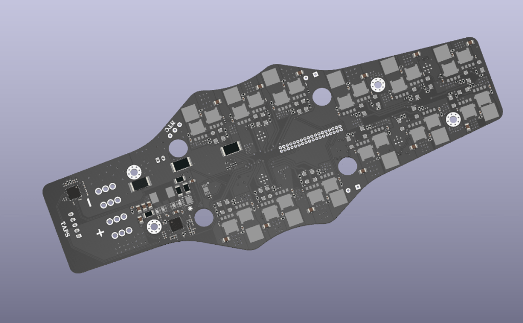
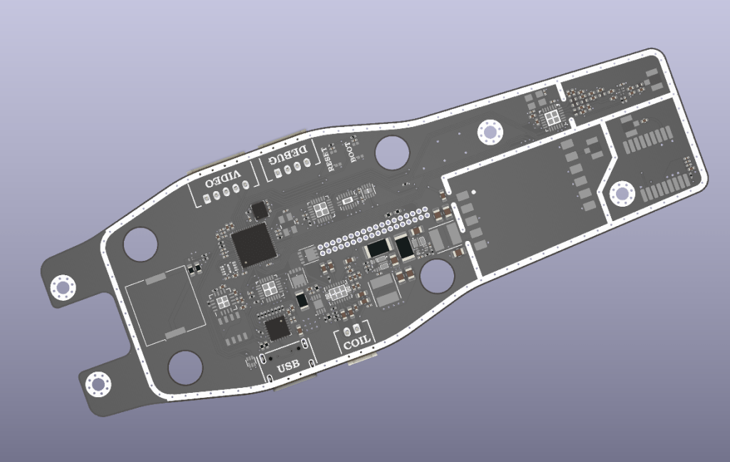
Wirelessly Charging Drone
This is a capstone project worked on by myself and two other people. The aim is to create a drone that can charge wirelessly and that can be controlled over the internet through a base station. I am responsible for the following portions of the design:
Drone
- 4s1p LiPo battery management system
- 120W-capable charge controller
- 5W WPC 1.2 compliant wireless power receiver
Base Station
- NTSC to MIPI video digitizer
- 15W WPC 1.2 compliant wireless power transmitter (jointly owned with one other person)
As of right now, the PCBs for the drone have been ordered, however the base station is still in the schematic phase.
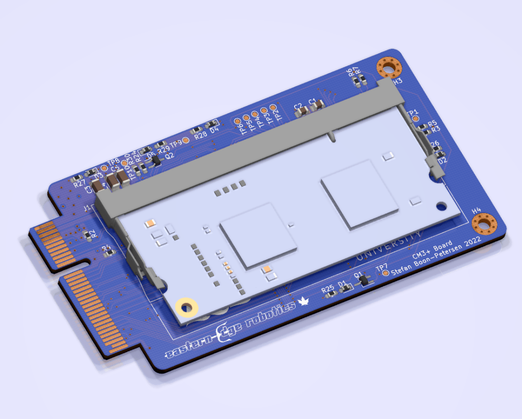


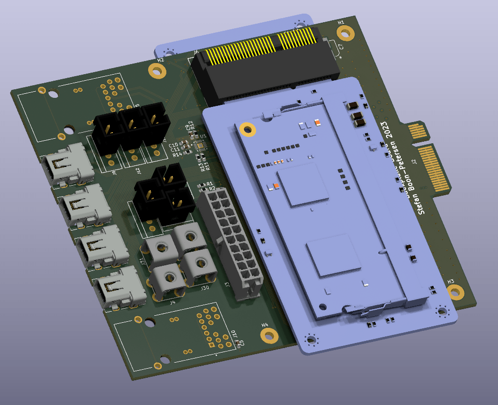
Compute Module Board (CM3+ Board)
This board was designed and built for Eastern Edge Robotics (EER). It is designed to connect the Raspberry Pi Compute Module 3+ to the ROV’s electrical system using its PCB edge connector. In addition to the compute module, the board contains the following:
- USB Hub
- USB to Ethernet Converter
- SPI to CAN converter
- CAN transciever
- Multiplexer to enable UART communications with multiple microcontrollers

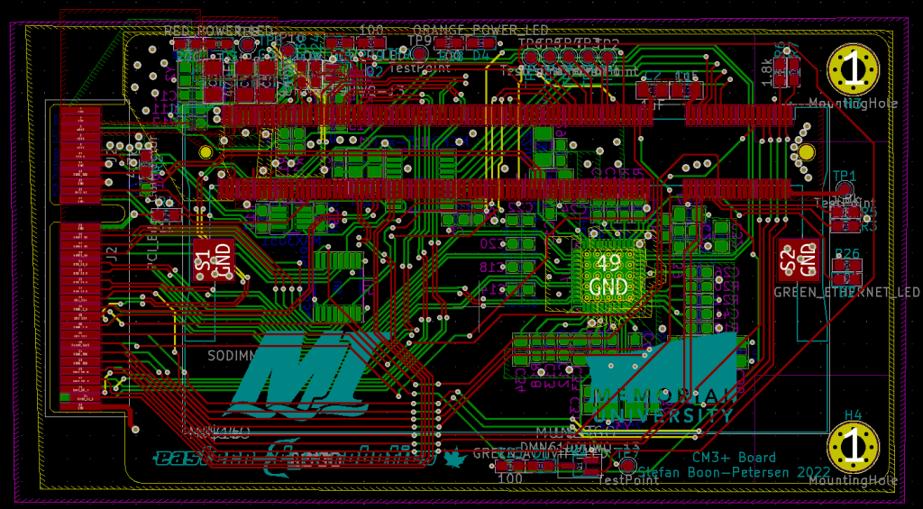
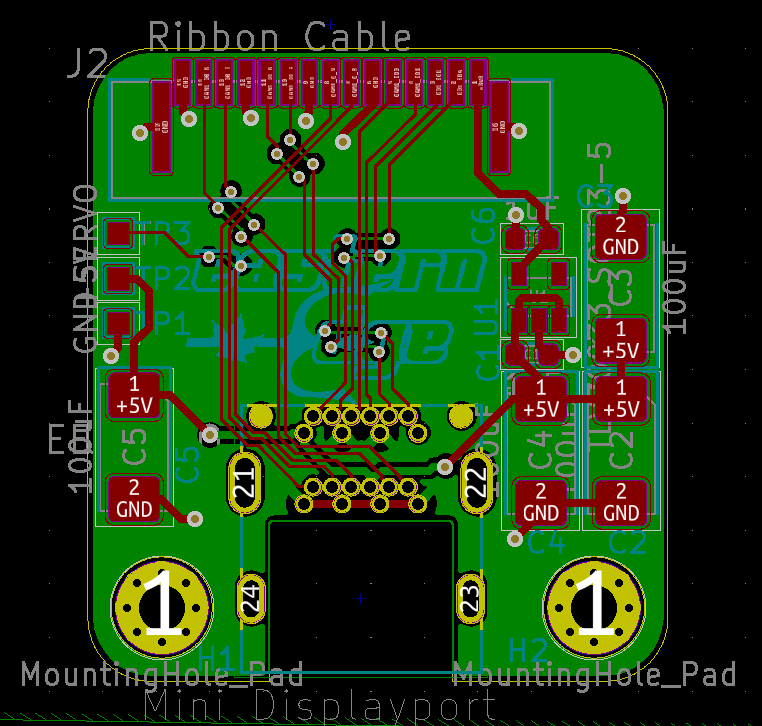
Backplane Board
This board was designed for EER and is in the process of being built. It is designed to hold two CM3+ boards (shown above). It uses its PCB edge connector to receive power from the ROV’s power conversion board and distribute it to both CM3+ boards. The board has two ethernet connectors (one for each CM3+ board). It has four mini-displayport connectors (2 for each CM3+ board) to connect the camera adapter boards to the Raspberry Pis. It also has a 20-pin connector to connect to the ROV’s tooling board and it contains several other connectors to connect to sensors onboard the ROV.
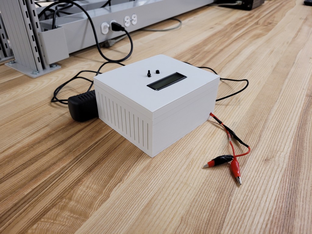
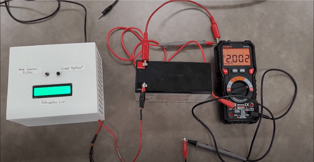
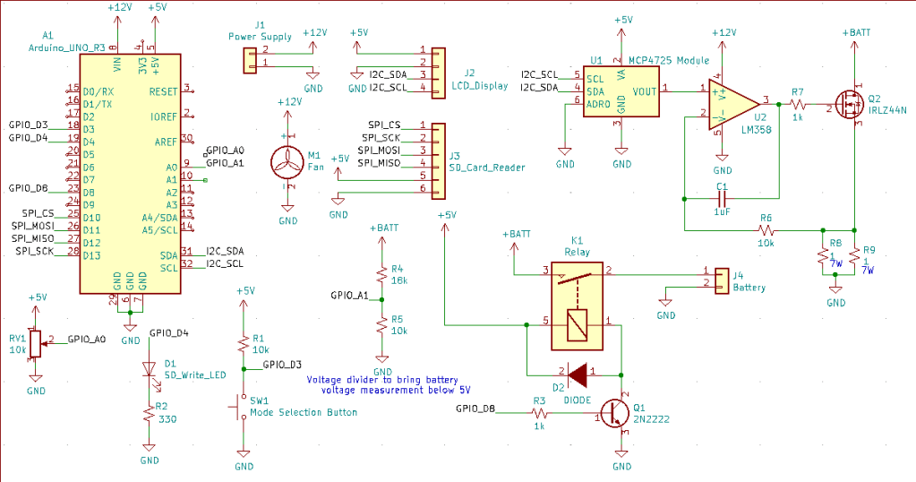
Battery Capacity Tester
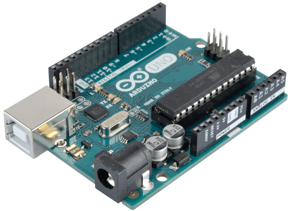
This battery capacity tester is designed to test the capacity of 12V lead-acid batteries by drawing a constant current from the battery until it is fully depleted. It uses a constant current sink circuit to maintain the same current draw as the battery voltage drops. This allows it to determine the battery capacity in both milliamp-hours and watt-hours. The current draw is user-adjustable between 0 and 5 A. The battery voltage is recorded to an SD card once every minute so that the battery performance can be analyzed after the test has finished. The tester is controlled using an Arduino Uno.

Camera Adapter Board
This board was designed and built for EER. EER uses Raspberry Pi Camera V2s that are mounted to a servo to allow for camera rotation. This board is designed to connect the Pi Camera’s ribbon cable to a mini-displayport cable to lower the cable size. It also has a 3-pin connection for the servo.
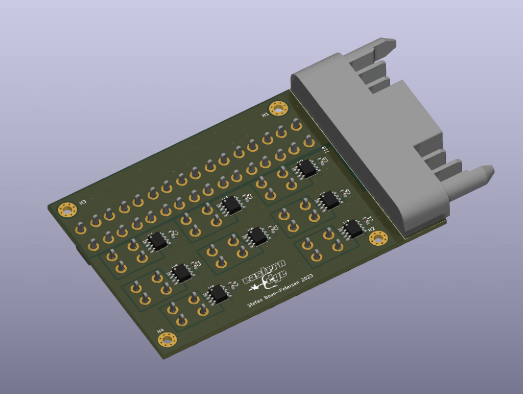
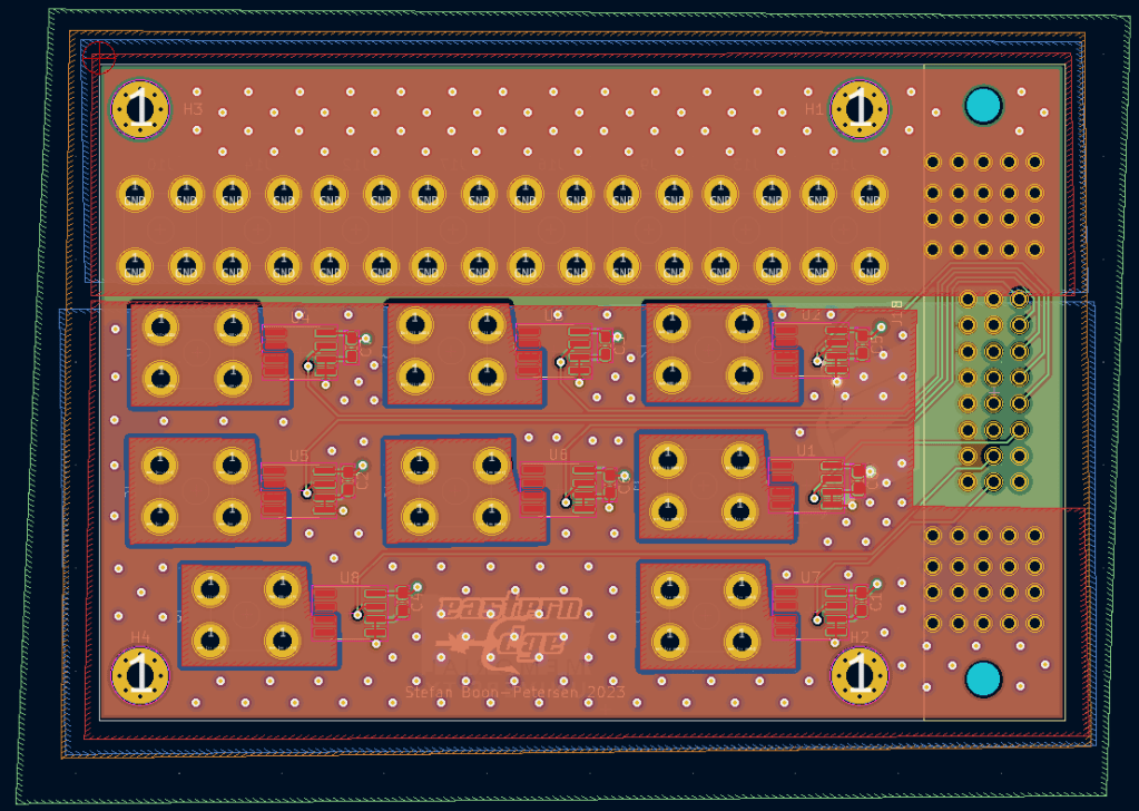
ESC Adapter Board
This board was designed for EER and is currently being built. It is designed to connect to the ROV’s voltage conversion board using the board-to-board connector. It distributes 12V to all 8 motor speed controllers onboard the ROV. Each of the 8 power connections has a current sensor so that the current draw of each motor can be monitored. The board is capable of handling over 100A.


Vertical Profiler
The vertical profiler was designed and built for EER for the 2022 MATE ROV competition. It is designed to move up and down in the water by adjusting its density (using a buoyancy engine). It adjusts its density by pulling in and pushing out water using a syringe. The on-board electrical system consists of batteries, a 3.3V linear regulator, an H-Bridge motor driver, and an Arduino Nano.
Arduino Quadcopter Control
This project was a proof-of-concept demonstration of quadcopter control software. It used an IMU to determine the orientation of the drone, and would adjust the thrust applied to each motor to maintain level flight. Each motor’s power output was recorded and graphed in real-time.
